Typical Bedroom Wiring Diagram
The electrical installation of a house or building is one of the key points of its structure. It must comply with a series of regulations and technical specifications that guarantee its installation and operation.
You will agree that an electrical installation must be configured according to safety and comfort criteria that ensure the optimum operation of the installation.
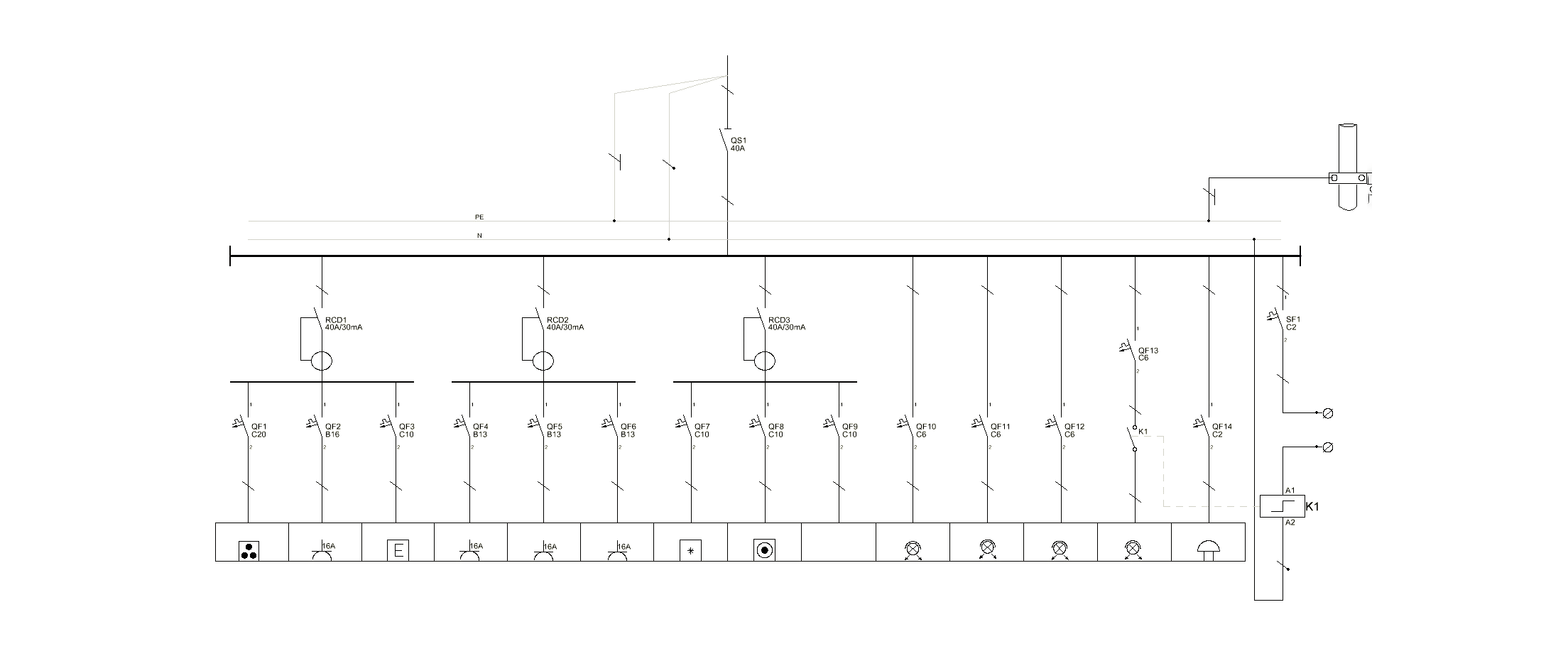
To represent an electrical installation there are different alternatives. In this case, we will focus on one of the most common and currently used: the single-line diagram

WHAT IS A SINGLE-LINE DIAGRAM
The single-line diagram is a graphical representation of an electrical installation. It differs from other diagrams because, in the case of the Single Line diagram, each circuit is represented by a single line, in which all the conductors of the corresponding section are represented.
BASIC ELEMENTS OF A SINGLE-LINE DIAGRAM
Following the standard electrical symbolism, the basic elements of the installation will be represented in the single-line diagram. In some of them we could even find more sophisticated elements, more typical of more complex schemes.
DISTRIBUTION PANEL
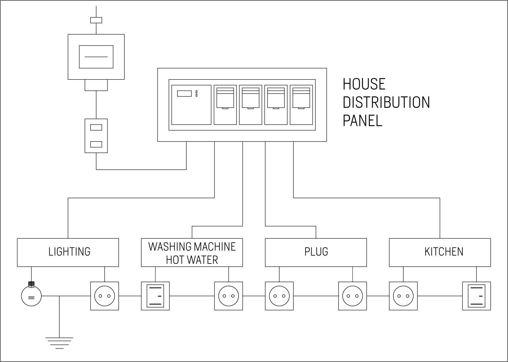
The distribution panel contains the elements for the protection and control of the electricity supply of the house. The electrical system is organized from this panel and the power of the installation is distributed.
In the single-line diagram the electrical panel is usually represented by a rectangle drawn with a dotted line.
CIRCUITS
A regular house usually has at least 5 circuits. In the single-line diagram we will see them represented as a line in which all the conductors are included.
The top end usually corresponds to the start of the scheme. The lower end is usually connected to another circuit or to a receiver.
- First circuit: controls lighting and illumination (intensity 10A)
- Second circuit: shows most of the plugs (16A current)
- Third circuit: represents the kitchen and bathroom sockets (intensity 16A)
- Fourth circuit: for the oven (intensity 25A)
- Fifth circuit: it brings together the washing machine and washing appliances (intensity 20A)

ELECTRICAL RECEIVERS
Electrical receivers represent all devices that are plugged in, whether they are thermal, such as stoves, irons, ovens, etc.; or luminous, such as lamps
POWER CIRCUIT BREAKER
The function of the Power Circuit Breaker is cutting off the flow of electricity to the installation in the event of a short circuit or an overvoltage. This switch monitors that the maximum bearable by the installation is not exceeded
RESIDUAL-CURRENT DEVICE
Its function can be confused with that of the IGA, since the Residual-Current Device also cuts off the installation, but for a different reason. The Residual-Current Device is responsible for protecting the installation against possible current leaks.
In the case that you cut off the installation, this will be because of an earth leak or because some electrical appliance is defective
MINIATURE CIRCUIT BREAKER (MCB)
MCBs are responsible for protecting electrical circuits against overloads and short circuits. They have:
- A magnetic trigger that is activated when the current exceeds its nominal value
- A thermal disconnector, which disconnects the electrical flow if it overheats.
DISTRIBUTION BOARD
It is in the Distribution board where the safety, control and protection elements are located. It is normally close to the access door to the house
STANDARD ELECTRICAL SYMBOLISM
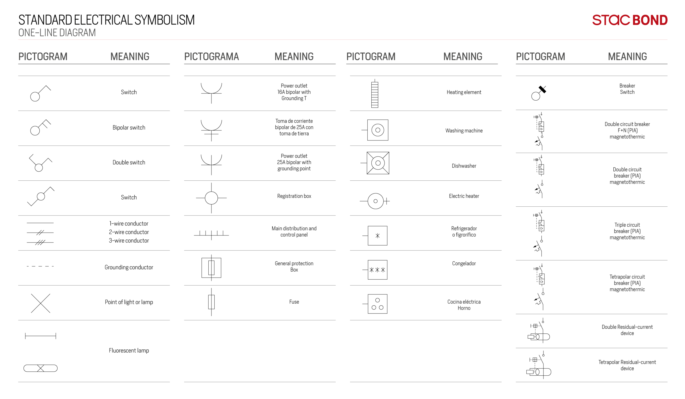
The electrical symbolism represented in the single-line diagrams follows the international standard IEC 60617, which has been adopted both at European and Spanish level, with the standard UNE-EN 60617.
This standard is divided into different parts, which are as follows:
- Conductors, passive components, basic control and protection elements
- Power switching devices, relays, contacts and drives
- Measuring and signalling instruments
- Production, transformation and conversion of electrical energy
- Semiconductors
- Analogue operators
- Binary logic operators
In the following diagram you will find the most common representations that you will see in a single-line diagram:

COMFORT STANDARDS
The standards for electrical installations in homes take into account what are called minimum and comfort requirements, which recommend, among other aspects, that the design of the installation take into account the particular needs of each user, paying special attention to future needs.
This includes leaving enough space for new installations or increasing the number of circuits and points in the installation. In the case of houses of more than one height, it is advisable to place an electrical panel in each one, so that the circuits are controlled and protected from their respective panel.
It is also advisable to install the maximum number of sockets per circuit, and to add several sockets to each TV and telephone plug, taking into account the increasing use of electronic devices. In addition to comfort, it increases safety as the user does not need to install power strip (extension block).
SINGLE-LINE DIAGRAM FOR AUTOCAD
Thanks to the large amount of resources currently available on the network for AutoCAD, it is possible to obtain detailed single-line diagrams for homes.
These types of files, as we saw in our previous post about what AutoCAD is and what it is for, are usually available in virtual resource libraries. It is the easiest and fastest way to add a reliable single-line diagram to your project.
Single-line diagram for Autocad
With this help for AutoCAD we end this post. We hope that we have helped you to understand what a single-line diagram is and how it is represented in the plans of a house.
Typical Bedroom Wiring Diagram
Source: https://stacbond.com/en/single-wire-diagram-how-to-represent-the-electrical-installation-of-a-house/

0 Komentar